从晶元到人工智能
我们在控制模块中所使用的处理器是Cortex-M4系列中的STM32F407VE,这个处理器芯片有100个引脚,其中包含一些电源供电引脚、外部晶振引脚、SWD程序烧录引脚和我们最常用的GPIO功能引脚:
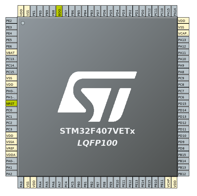
实际上,我们使用的GPIO并不多,我们只使用了3路AD采集、Uart1和Uart2、I2C1、Tim3和Tim4的PWM输出引脚以及几个普通GPIO脚(具体使用情况请参照《控制模块》)。STM32中有丰富的硬件资源供我们使用,例如:AD采集、串口、I2C、SPI、SDIO、CAN、USB_OTG_FS、USB_OTG_HS、I2S、PWM输出、PWM采集、GPIO输入输出等。在这一节里我们将完成STM32的第一个小程序:点亮LED灯。
一、开发环境搭建:
我们的整个项目都会在Linux系统下完成,因此后续所有章节中如无特殊说明,我们都默认在Linux下搭建所有的开发环境。
首先,我们需要下载并安装在Arm平台下的gcc编译工具arm-none-eabi-gcc。作者所使用的Linux发行版为Arch-Linux,可以直接使用下面命令进行安装:
#Arch-Linux
pacman -S arm-none-eabi-gcc

#Fedora
yum install arm-none-eabi-gcc

#ubuntu
apt-get install arm-none-eabi-gcc
一般来说,其它Linux的发行版都有着自己的安装软件包的方式,我们不再一一列举。此外,我们还可以直接在GNU的网站上直接下载压缩包:
我们下载Linux x86_64 Tarball压缩包,解压到指定目录,并将其目录加入到PATH环境变量中,最后执行以下命令的查看是否安装成功:
$ arm-none-eabi-gcc --version
arm-none-eabi-gcc (GNU Tools for ARM Embedded Processors) 5.4.1 20160919 (release) [ARM/embedded-5-branch revision 240496]
Copyright (C) 2015 Free Software Foundation, Inc.
This is free software; see the source for copying conditions.  There is NO
warranty; not even for MERCHANTABILITY or FITNESS FOR A PARTICULAR PURPOSE.
其次,我们还需要使用STM32F4xx的标准开发库,我们可以到STM32官方的网站上下载:
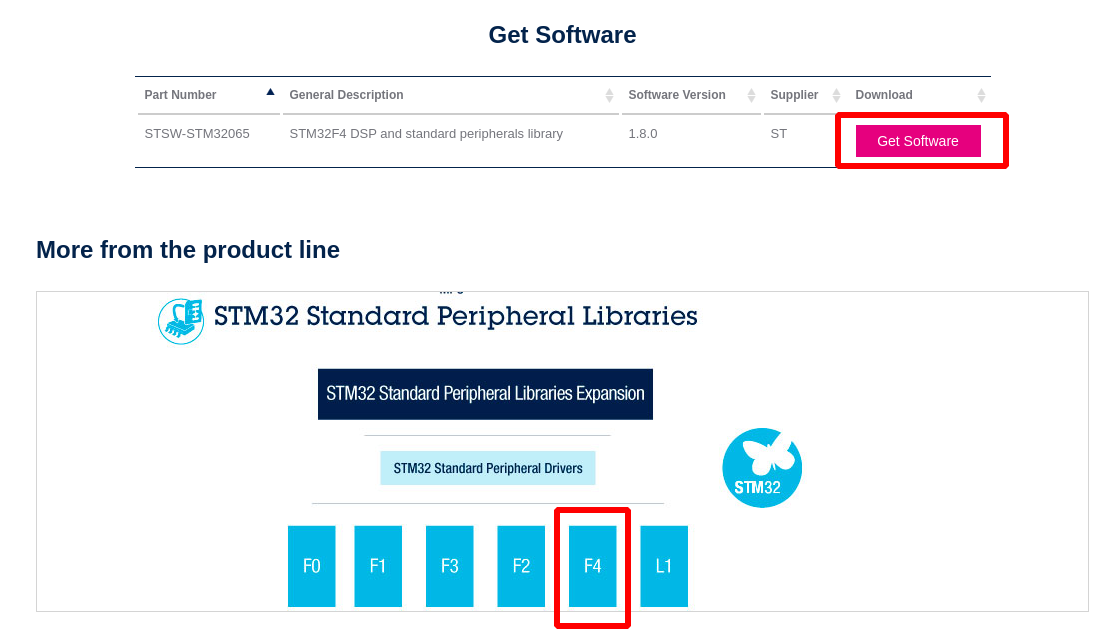
我们需要下载F4系列的标准开发库,下载并解压之后,得到以下目录:
├── CMSIS
│   ├── Device
│   └── Include
└── STM32F4xx_StdPeriph_Driver
    ├── inc
    └── src
这样我们的开发环境就准备好了,接下来就可以在这个开发不环境下进行开发了。
二、点亮LED灯:
使用arm gcc来编译STM32所运行的程序,我们需要编写一个Makefile如下:
# Output files
ELF_FILE	=	led.elf
BIN_FILE	=	led.bin
HEX_FILE	=	led.hex
INFO_FILE	=	led.info
CODE_FILE	=	led.code

#------------------------------------------------------------------------#
# Cross Compiler
CC			=	arm-none-eabi-gcc
OBJCOPY		=	arm-none-eabi-objcopy
OBJDUMP		=	arm-none-eabi-objdump
READELF		=	arm-none-eabi-readelf

#------------------------------------------------------------------------#
# Flags
CFLAGS		+=	-std=gnu11
CFLAGS		+=	-mthumb
CFLAGS		+=	-Wno-incompatible-pointer-types
CFLAGS		+=	-Wno-unused-but-set-variable
CFLAGS		+=	-Wno-unused-variable
CFLAGS		+=	-mcpu=cortex-m4
CFLAGS		+=	-mfpu=fpv4-sp-d16 -mfloat-abi=hard
CFLAGS		+=	-D"assert_param(expr)=((void)0)"
CFLAGS		+=	-D STM32F40XX -DUSE_STDPERIPH_DRIVER
CFLAGS		+=	-nostartfiles

#------------------------------------------------------------------------#
# Link script
CFLAGS		+=	-Wl,-Tled.ld

#------------------------------------------------------------------------#
# Libraries
STM32_LIBS	=	libs/STM32F4xx_StdPeriph_Driver
CFLAGS		+=	-I$(STM32_LIBS)/inc
CFLAGS		+=	-Ilibs/CMSIS/Include
CFLAGS		+=	-Ilibs/CMSIS/Device/ST/STM32F4xx/Include

#------------------------------------------------------------------------#
# Src Path
SRCS		=	./src
CFLAGS		+=	-I$(SRCS)
CFLAGS		+=	-I./inc

#------------------------------------------------------------------------#
# Main Board
SRC			+=	$(SRCS)/main.c

#------------------------------------------------------------------------#
# System
SRC			+=	./src/system_stm32f4xx.c

STARTUP		=	./src/startup_stm32f40xx.s

#------------------------------------------------------------------------#
# StdPeriph
SRC			+=	$(STM32_LIBS)/src/misc.c \
				$(STM32_LIBS)/src/stm32f4xx_rcc.c \
				$(STM32_LIBS)/src/stm32f4xx_gpio.c

STARTUP_OBJ	=	startup_stm32f40xx.o

all:$(BIN_FILE) $(HEX_FILE) $(INFO_FILE) $(CODE_FILE)

$(BIN_FILE):$(ELF_FILE)
	$(OBJCOPY) -O binary $^ $@

$(HEX_FILE):$(ELF_FILE)
	$(OBJCOPY) -O ihex $^ $@

$(INFO_FILE):$(ELF_FILE)
	$(READELF) -a $^ > $@

$(CODE_FILE):$(ELF_FILE)
	$(OBJDUMP) -S $^ > $@

$(STARTUP_OBJ):$(STARTUP)
	$(CC) $(CFLAGS) $^ -c $(STARTUP)

$(ELF_FILE):$(SRC) $(STARTUP_OBJ)
	$(CC) $(CFLAGS)	$^ -o $@
之后,我们还需要编写一个led.ld的链接脚本,内容如下:
/* Entry Point */
ENTRY(Reset_Handler)

/* Highest address of the user mode stack */
_estack = 0x20020000;    /* end of 128K RAM on AHB bus*/

/* Generate a link error if heap and stack don't fit into RAM */
_Min_Heap_Size = 0;      /* required amount of heap  */
_Min_Stack_Size = 0x400; /* required amount of stack */

/* Specify the memory areas */
MEMORY
{
  FLASH (rx)      : ORIGIN = 0x08000000, LENGTH = 512K
  RAM (xrw)       : ORIGIN = 0x20000000, LENGTH = 128K
  CCMRAM (rw)     : ORIGIN = 0x10000000, LENGTH = 64K
}

/* Define output sections */
SECTIONS
{
	.myBufBlock 0x10000000 :
    {
        KEEP(*(.myBufSection)) /* keep my variable even if not referenced */
    } > CCMRAM

  /* The startup code goes first into FLASH */
  .isr_vector :
  {
    . = ALIGN(4);
    KEEP(*(.isr_vector)) /* Startup code */
    . = ALIGN(4);
  } >FLASH

  /* The program code and other data goes into FLASH */
  .text :
  {
    . = ALIGN(4);
    *(.text)           /* .text sections (code) */
    *(.text*)          /* .text* sections (code) */
    *(.rodata)         /* .rodata sections (constants, strings, etc.) */
    *(.rodata*)        /* .rodata* sections (constants, strings, etc.) */
    *(.glue_7)         /* glue arm to thumb code */
    *(.glue_7t)        /* glue thumb to arm code */
	*(.eh_frame)

    KEEP (*(.init))
    KEEP (*(.fini))

    . = ALIGN(4);
    _etext = .;        /* define a global symbols at end of code */
    _exit = .;
  } >FLASH


   .ARM.extab   : { *(.ARM.extab* .gnu.linkonce.armextab.*) } >FLASH
    .ARM : {
    __exidx_start = .;
      *(.ARM.exidx*)
      __exidx_end = .;
    } >FLASH

  .preinit_array     :
  {
    PROVIDE_HIDDEN (__preinit_array_start = .);
    KEEP (*(.preinit_array*))
    PROVIDE_HIDDEN (__preinit_array_end = .);
  } >FLASH
  .init_array :
  {
    PROVIDE_HIDDEN (__init_array_start = .);
    KEEP (*(SORT(.init_array.*)))
    KEEP (*(.init_array*))
    PROVIDE_HIDDEN (__init_array_end = .);
  } >FLASH
  .fini_array :
  {
    PROVIDE_HIDDEN (__fini_array_start = .);
    KEEP (*(.fini_array*))
    KEEP (*(SORT(.fini_array.*)))
    PROVIDE_HIDDEN (__fini_array_end = .);
  } >FLASH

  /* used by the startup to initialize data */
  _sidata = .;

  /* Initialized data sections goes into RAM, load LMA copy after code */
  .data : AT ( _sidata )
  {
    . = ALIGN(4);
    _sdata = .;        /* create a global symbol at data start */
    *(.data)           /* .data sections */
    *(.data*)          /* .data* sections */

    . = ALIGN(4);
    _edata = .;        /* define a global symbol at data end */
  } >RAM

  /* Uninitialized data section */
  . = ALIGN(4);
  .bss :
  {
    /* This is used by the startup in order to initialize the .bss secion */
    _sbss = .;         /* define a global symbol at bss start */
    __bss_start__ = _sbss;
    *(.bss)
    *(.bss*)
    *(COMMON)

    . = ALIGN(4);
    _ebss = .;         /* define a global symbol at bss end */
    __bss_end__ = _ebss;
  } >RAM

  /* User_heap_stack section, used to check that there is enough RAM left */
  ._user_heap_stack :
  {
    . = ALIGN(4);
    PROVIDE ( end = . );
    PROVIDE ( _end = . );
    . = . + _Min_Heap_Size;
    . = . + _Min_Stack_Size;
    . = ALIGN(4);
  } >RAM

  /* Remove information from the standard libraries */
  /DISCARD/ :
  {
    libc.a ( * )
    libm.a ( * )
    libgcc.a ( * )
  }

  .ARM.attributes 0 : { *(.ARM.attributes) }
}
最后,我们编写程序源代码文件main.c,实现LED亮灯功能:
#include <stm32f4xx.h>
#include <stm32f4xx_conf.h>

int main(int argc, char* argv[])
{
	GPIO_InitTypeDef GPIO_InitStructure = { 0 };
	RCC_AHB1PeriphClockCmd(RCC_AHB1Periph_GPIOE, ENABLE);
	GPIO_InitStructure.GPIO_Mode = GPIO_Mode_OUT;
	GPIO_InitStructure.GPIO_Pin = GPIO_Pin_0 | GPIO_Pin_1;
	GPIO_InitStructure.GPIO_Speed = GPIO_Speed_50MHz;
	GPIO_Init(GPIOE, &GPIO_InitStructure);

	GPIO_WriteBit(GPIOE, GPIO_Pin_0, 0);
	GPIO_WriteBit(GPIOE, GPIO_Pin_1, 0);

	while (1)
	{
	}
}
需要说明的是,我们先来看一下LED电路的原理图:
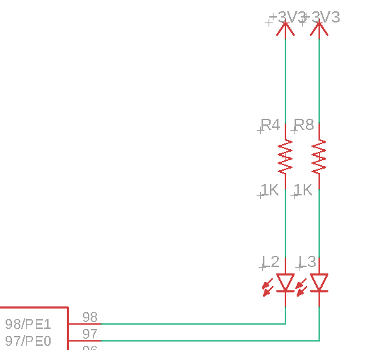
可以看到两个LED分别使用的是PE0和PE1引脚,当引脚为低电平时LED灯亮起,当引脚为高电平时LED熄灭,因此,当我们希望LED亮起只需要通过GPIO_WriteBit()函数将PE0和PE1拉低即可。
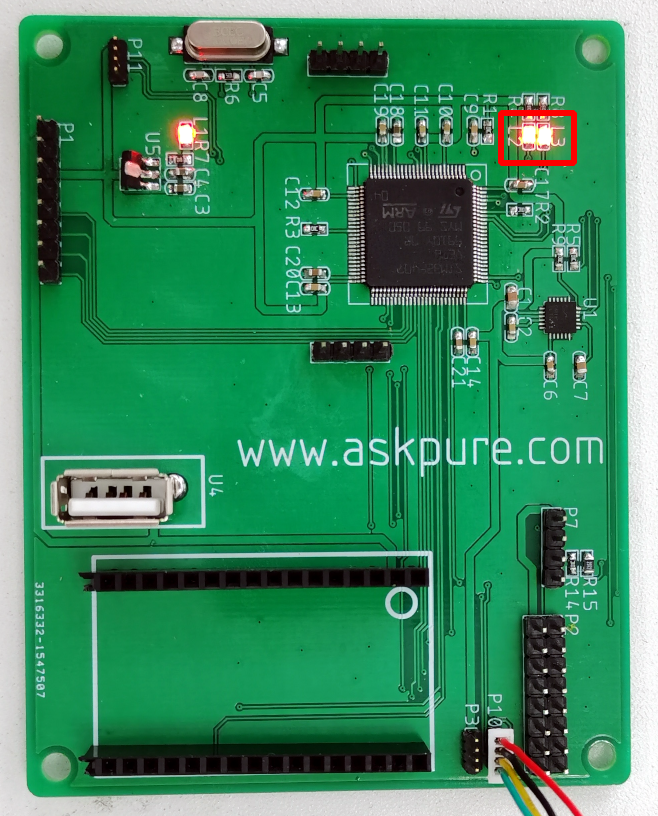
点亮了两个LED之后,我们还可以将源代码修改一下,让LED变为闪烁状态:
#include <stm32f4xx.h>
#include <stm32f4xx_conf.h>

int main(int argc, char* argv[])
{
	GPIO_InitTypeDef GPIO_InitStructure = { 0 };
	RCC_AHB1PeriphClockCmd(RCC_AHB1Periph_GPIOE, ENABLE);
	GPIO_InitStructure.GPIO_Mode = GPIO_Mode_OUT;
	GPIO_InitStructure.GPIO_Pin = GPIO_Pin_0 | GPIO_Pin_1;
	GPIO_InitStructure.GPIO_Speed = GPIO_Speed_50MHz;
	GPIO_Init(GPIOE, &GPIO_InitStructure);

	while (1)
	{
		GPIO_WriteBit(GPIOE, GPIO_Pin_0, 1);
		GPIO_WriteBit(GPIOE, GPIO_Pin_1, 0);
		for (int i = 0; i < 1000000; i++)
		{
		}
		GPIO_WriteBit(GPIOE, GPIO_Pin_0, 0);
		GPIO_WriteBit(GPIOE, GPIO_Pin_1, 1);
		for (int i = 0; i < 1000000; i++)
		{
		}
	}
}
我们在while循环中加入两个for循环让处理器执行100000次实现程序“等待一小会儿”的功能,但实际上这段时间处理器还是在运行的,我们来看一下效果:
Copyright © 2015-2023 问渠网 辽ICP备15013245号